Address
Nanzhai village, Liushi Town, yueqingCity, zhejiang Province, china
Tel
+86-13375775325
Views: 0 Author: Site Editor Publish Time: 2026-09-23 Origin: Site

Picture 115,000 volts surging through an overhead cable just yards above a busy highway. Without proper insulation, the resulting catastrophic grid failure would happen in a fraction of a second. Lethal currents would shoot straight into the ground. Suspension insulators stand as the unsung heroes between that raw electrical power and the steel utility towers supporting the network.
Yet, the modern power grid is constantly under siege. Extreme weather, industrial pollution, and mechanical fatigue threaten grid stability on a daily basis. In this comprehensive guide, we will break down the exact physics, mechanics, and material science behind how these critical devices operate in the field. We will place a specific focus on the current industry standard: the composite polymer insulator.
Dual Functionality: These devices perform two critical engineering tasks simultaneously. They provide immense mechanical tensile strength to support heavy conductive cables while offering high-level electrical isolation to prevent current from discharging into the grounded transmission tower.
Material Evolution: Historically, utility grids relied on heavy glass and porcelain. Today, the composite suspension insulator represents the industry standard. Field engineers favor them for their lightweight profile, superior pollution resistance, and physical resilience.
Anatomy of Success: The reliability of modern units relies on an advanced fiberglass core for unyielding tensile strength. This core is surrounded by a polymer housing that provides vital environmental protection and water-repelling properties.
Voltage Scalability: For high-voltage and extra-high-voltage networks, engineers deploy a continuous long rod design. This effectively manages severe electrical stress without the mechanical burden of stacking dozens of heavy porcelain discs.
At its core, a suspension insulator is a critical grid component hung from the cross-arm of a transmission tower. Its primary function is to physically support the high-voltage line conductor suspended below it while maintaining a strict electrical barrier. Unlike pin insulators, which support lines from below and are typically limited to lower distribution voltages, suspension configurations are designed to handle immense mechanical tension. Consequently, utility crews primarily deploy them on overhead transmission lines operating above 33kV.
The fundamental problem this device solves is rooted in basic physics. High-voltage electrical current constantly seeks the path of least resistance to the earth. In a transmission network, the steel tower represents that direct path. By acting as an impenetrable dielectric barrier, the insulator physically separates the energized conductor from the grounded tower structure. This ensures that the electricity remains safely within the wire, traveling to its intended destination rather than causing a catastrophic flashover.
To truly understand how this equipment functions in the field, one must examine the specific physical and electrical forces it counteracts daily. It is a constant battle against both voltage and gravity.
Even with high-quality dielectric materials, a phenomenon known as leakage current can occur. When dust, coastal salt spray, or industrial smog settles on the surface of an insulator and becomes damp from rain or morning fog, it creates a conductive film. Electricity attempts to travel across this moist surface from the live conductor to the grounded tower.
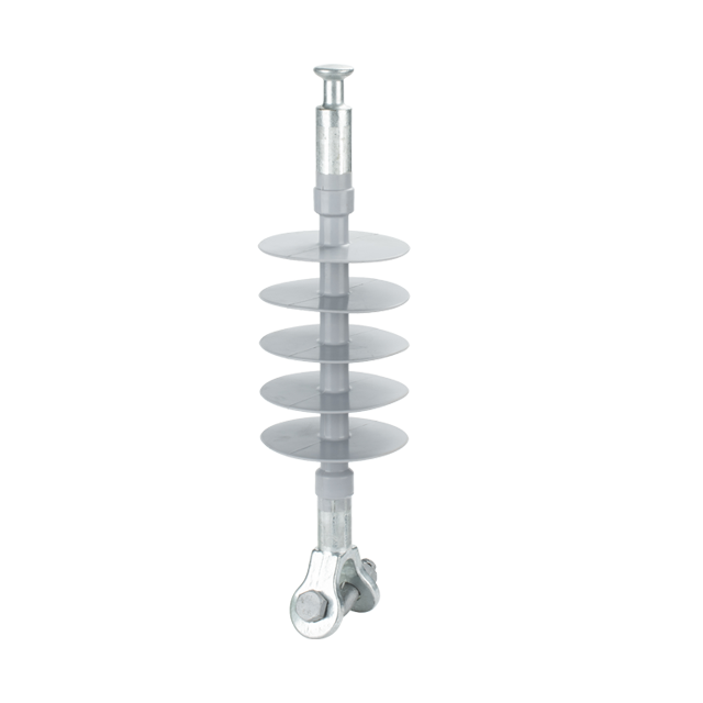
To prevent this surface tracking, insulators feature molded ridges visible along the outer shaft. These sheds serve a vital mathematical purpose. They drastically increase the creepage distance. Creepage distance is defined as the shortest path along the surface of the insulator that electricity must travel to cause a flashover. By alternating the diameter and angle of these sheds, engineers maximize the surface distance without increasing the overall length of the unit. If the creepage distance is sufficient for the specific environmental pollution level, the leakage current is safely interrupted.
Beyond electrical resistance, these units are structural load-bearing devices that must withstand extreme, continuous physical stress. The primary force is the dead weight of the conductor itself, spanning hundreds of meters between towers.
Furthermore, dynamic loads present the greatest engineering challenge. During bitter winter storms, ice accumulation can exponentially increase the weight of the cables. In addition, extreme wind shear creates violent lateral forces and galloping effects on the lines. The insulator must absorb these mechanical shocks and maintain its structural integrity under thousands of pounds of tensile force without stretching, cracking, or snapping.
In high-voltage applications, electrical stress is not distributed equally across the length of the string. Because of stray capacitance between the insulator components and the grounded metal tower, the segment closest to the live conductor experiences significantly higher electrical pressure than the segments closer to the tower.
This uneven distribution is measured as string efficiency. If left unmitigated, the severe electrical stress at the conductor end leads to localized corona discharge, which degrades the insulating material over time. Modern designs mitigate this by utilizing metal corona rings at the energized end. These rings reshape the electrical field, distributing the voltage gradient more evenly and preventing localized material degradation.
The operational success of polymer technology is not due to a single miracle material. Rather, it comes from the precise engineering of three distinct components working in perfect unison.
The internal structural foundation of the device is the FRP core rod suspension insulator design. Manufactured through a highly controlled pultrusion process, thousands of continuous, boron-free glass fibers are impregnated with an epoxy resin and cured under intense heat.
This creates a central rod that possesses an exceptional strength-to-weight ratio, often surpassing structural steel. Because the glass fibers run continuously from end to end, the rod can sustain massive tension loads. Depending on the specification, these core rods frequently exceed mechanical loads of 70kN to 120kN without structural fatigue. Crucially, this core is electrically non-conductive, ensuring the structural backbone does not compromise the unit's dielectric integrity.
While the fiberglass core provides immense strength, it is highly susceptible to degradation from moisture and ultraviolet radiation. To protect it, the core is seamlessly encapsulated within a polymer housing. Utilizing a silicone rubber suspension insulator offers significant field advantages, primarily due to a unique chemical property called hydrophobicity.
Hydrophobicity refers to the material's ability to repel water. When rain hits high-temperature vulcanized silicone rubber, it does not form a continuous, conductive film. Instead, the water beads up into isolated droplets and rolls off the sheds. More impressively, silicone exhibits a hydrophobicity transfer capability. Low molecular weight siloxanes within the rubber naturally migrate to the surface, encapsulating dirt and pollution particles. This means even when the insulator is covered in grime, the surface remains water-repellent, drastically reducing the risk of wet flashovers in highly polluted environments.
The final components are the metal end fittings, which serve as the physical anchors connecting the insulator to the tower structure and the conductor clamp. Typically forged from hot-dip galvanized steel or high-strength aluminum alloys, these fittings come in standard configurations such as clevis, tongue, ball, or socket.
The critical engineering phase here is the attachment process. The metal fittings are mechanically crimped onto the ends of the fiberglass core. This crimping must be executed with absolute precision. Insufficient pressure will lead to the conductor slipping under heavy ice loads. Conversely, excessive pressure can cause micro-fractures in the fiberglass, leading to internal mechanical failure. Leading manufacturers use multi-directional acoustic emission monitoring during crimping to ensure a flawless, secure bond.
Historically, managing higher transmission voltages meant utilizing a modular approach. A single porcelain disc can only insulate a specific voltage, usually around 11kV. To insulate a 132kV or 220kV line, field engineers had to physically link multiple heavy discs together using metal ball-and-socket joints to create a long string.
While functional, this traditional method introduces multiple points of failure. Every metal joint between the discs is a concentrated area of electrical and mechanical stress. Furthermore, porcelain is susceptible to internal electrical punctures, where sudden voltage surges such as lightning strikes blast a conductive hole directly through the ceramic material.
The modern solution to this structural inefficiency is the composite long rod insulator. Instead of stacking individual components, this design utilizes a single, continuous fiberglass core covered by a unified silicone housing, regardless of the required length.
This continuous design offers profound operational benefits. Specifically, it eliminates all intermediate metal connecting pins, drastically reducing the concentration of electrical stress along the shaft. Because the core is a solid, void-free cylinder, it is essentially puncture-proof. Electrical surges are forced to travel over the exterior surface rather than puncturing through the core. Finally, replacing a heavy string of 15 porcelain discs with a single composite rod reduces the total weight of the installation by up to 90 percent.
For procurement managers and transmission engineers, selecting the right insulation infrastructure is a critical decision. The choice directly impacts capital expenditure, operational expenditure, and overall grid reliability. To understand why utility companies are aggressively transitioning to polymer technologies, we must evaluate the empirical differences.
Feature | Traditional Porcelain Insulators | Composite Polymer Insulators |
|---|---|---|
Weight & Logistics | Extremely heavy. Requires cranes, heavy machinery, and extensive labor to hoist into position. | Up to 90% lighter. Can often be maneuvered manually by linemen, speeding up installation. |
Impact Resistance | Highly brittle. Prone to chipping during transport and shattering from vandalism. | Flexible and shatterproof. Absorbs physical impacts without compromising the core. |
Pollution Performance | Poor in coastal or industrial areas. Requires frequent, expensive helicopter washing to prevent flashovers. | Excellent. Silicone rubber is naturally hydrophobic and self-cleaning, drastically reducing maintenance. |
Puncture Risk | Susceptible to internal punctures from lightning strikes or high-voltage surges. | Virtually puncture-proof due to the continuous, void-free fiberglass core design. |
An analysis of current grid infrastructure trends reveals a massive industry pivot toward climate resilience. As extreme weather events ranging from unprecedented ice storms to category 5 hurricanes become more frequent, utility operators can no longer rely on brittle legacy materials. The structural rigidity of porcelain often leads to catastrophic tower failures during high-wind line galloping events.
Consequently, the global market is seeing an accelerated adoption of polymer-based equipment. Their ability to flex under severe dynamic loads without snapping, combined with their resistance to pollution-induced flashovers during volatile weather shifts, makes them a cornerstone of modern grid hardening strategies. Regulatory bodies are increasingly mandating these advanced materials for new transmission interconnects to ensure long-term energy security and reduce grid downtime.
The reliability of a transmission network is only as strong as its manufacturing quality and maintenance protocols. Understanding the lifecycle of these devices provides engineers with the confidence required for large-scale procurement.
The lifecycle begins with precision manufacturing. Top-tier manufacturers utilize high-temperature, high-pressure single-shot injection molding to apply the silicone housing. This over-molding technique chemically bonds the silicone to the core, ensuring a seamless, void-free interface. If microscopic air pockets were left between these materials, internal moisture ingress would lead to tracking, acid generation, and eventual brittle fracture.
During deployment, installation crews must adhere to strict handling protocols. Insulators should never be dragged across rough ground or gravel, as this can tear the delicate silicone sheds. When hoisting the unit, nylon slings must be used instead of steel cables, which can slice into the rubber. Protecting the hydrophobic surface during installation is paramount.
Once active, maintenance shifts from physical intervention to condition monitoring. Because they do not require routine washing, utility crews utilize daytime ultraviolet cameras to inspect lines for abnormal electrical discharges. As long as the silicone retains its water-repellent nature and shows no signs of physical erosion, a high-quality composite unit boasts an expected operational lifespan of 20 to 30 years.
Grid requirements vary wildly depending on whether you are routing power through a dense urban distribution network or transmitting massive loads across rural topographies. Selecting the correct voltage class, mechanical load, and creepage distance is paramount.
For medium voltage distribution networks ranging from 15kV to 24kV, the primary goal is maintaining reliable service while keeping the infrastructure lightweight to reduce utility pole strain. For example, a standard 24kV unit might feature a 70kN specified mechanical load and over 600mm of creepage distance. These units provide ample insulation for typical weather conditions while offering the fast, equipment-free installation that repair crews prefer during storm recovery efforts.
As voltages scale into the transmission tier of 115kV and above, the physics of electrical isolation become significantly more complex. For major regional transmission interconnects, deploying a 115kV silicone suspension insulator provides the robust mechanical tension required for long conductor spans, often requiring mechanical ratings of 120kN or higher. At these extreme voltage levels, corona rings become mandatory to equalize the electrical field and prevent the surrounding air from ionizing, which would otherwise degrade the polymer via ozone exposure.
A composite suspension insulator is a marvel of modern engineering, perfectly balancing heavy mechanical tension with impenetrable electrical resistance. By physically isolating live conductors from grounded towers, these devices keep our power grids safe from catastrophic short circuits.
Upgrading from legacy porcelain to advanced polymer materials is no longer just a trend. It is a critical requirement for climate-resilient grid modernization. They are logistically efficient, shatterproof, and require a fraction of the routine maintenance of their predecessors.
If you are planning an infrastructure upgrade, evaluating the lifecycle costs and mechanical benefits of polymer insulators is the first step toward a more reliable network. To ensure your next transmission line project meets the highest standards of safety and efficiency, explore the full range of advanced composite solutions at Langao Power. Contact their specialized engineering team today to discuss custom creepage requirements, verify mechanical loads, and request a tailored quote for your specific grid demands.
The primary difference lies in their mechanical application and voltage scalability. Pin insulators are mounted rigidly on top of a crossarm and support the conductor from below. They are generally limited to lower distribution voltages because higher voltages would require a pin insulator too large and heavy to be structurally sound. Suspension insulators, however, hang downward from the transmission tower crossarm and support the conductor from above. This flexible suspension design allows them to handle immense mechanical tension and scale to ultra-high voltages reaching 800kV and beyond by simply increasing the length of the unit.
Silicone rubber is utilized because of its exceptional water-repelling properties. When rain or fog hits a silicone surface, the water beads up into isolated droplets rather than forming a continuous, wet film. This prevents electrical current from leaking across the surface. Furthermore, silicone rubber contains low molecular weight siloxanes that migrate to the surface, transferring this hydrophobicity to any dirt or pollution that accumulates. This chemical reaction makes the unit virtually self-cleaning and highly resistant to wet flashovers.
FRP stands for Fiberglass Reinforced Plastic. It serves as the internal mechanical backbone of the insulator. Manufactured using a precise pultrusion process, high-strength glass fibers are bound together with an epoxy resin. This core provides extraordinary tensile strength, allowing a relatively thin rod to support thousands of pounds of dead weight, ice loads, and wind shear from the heavy transmission cables without snapping or deforming.
No, a true composite long rod insulator is essentially puncture-proof. Traditional porcelain disc insulators have metal pins and caps embedded within the dielectric material, creating a short distance through the solid material where high-voltage surges can punch a hole through the ceramic. A composite long rod utilizes a single, continuous fiberglass core from end to end with no intermediate metal fittings. Because the distance through the solid core is equal to the entire length of the insulator, an electrical surge will always flash over the outside air rather than puncturing the internal core.
When manufactured correctly and installed without damaging the silicone housing, high-quality composite suspension insulators have an expected operational lifespan of 20 to 30 years. Their longevity depends heavily on the environmental conditions, the level of ultraviolet exposure, and the severity of electrical stress. Routine inspections using ultraviolet cameras can help utilities monitor the condition of the polymer and plan for replacements before physical degradation compromises the line.
A flashover occurs when the electrical insulation breaks down, allowing current to arc through the air or across the surface of the insulator to the grounded tower. This is typically caused by a combination of severe surface pollution, such as salt or industrial dust, and moisture from fog or light rain. The moisture turns the pollution into a conductive path. Flashovers can also be triggered by sudden overvoltage events, such as lightning strikes or switching surges, which exceed the dielectric strength of the surrounding air.
While polymer units require minimal maintenance, signs of failure usually manifest on the silicone housing or end fittings. Visual indicators include tracking, which appears as carbonized black lines on the silicone caused by surface arcing. Erosion or severe chalking due to extreme ultraviolet degradation are also warning signs. Auditorily, a loud buzzing sound or a faint purple glow at night indicates severe corona discharge, which can rapidly degrade the polymer. Finally, any cracking or slippage at the metal end fittings indicates mechanical failure and requires immediate replacement to prevent line drops.